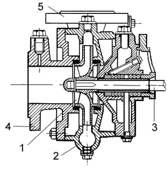
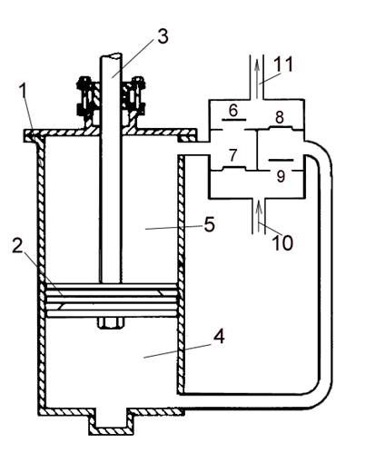
1. Rotor blindat (închis)
2. Camera spirală
3. Ax de antrenare
4. Flanșă de aspirație
5. Flanșă de refulare
Pumps - Constructive types
1. Rotor blindat (închis)
2. Camera spirală
3. Ax de antrenare
4. Flanșă de aspirație
5. Flanșă de refulare
1. Shrouded impeller
2. Volute casing
3. Driving shift
4. Suction flange
5. Discharge flange
Cel mai utilizat tip de pompă la bordul navei este pompa centrifugă. (fig. 1)
The most frequently used type of pump aboard of a ship is the centrifugal pump. (fig. 1)
La pompa centrifugă un important factor în funcționarea ei este acela că presiunea crește în rotor datorită forței centrifuge. O astfel de pompă constă dintr-un rotor care se rotește într-o carcasă. Fluidul intră în rotor în porțiunea centrală, numită ochiul, curge înspre exterior și este aruncată în jur pe toată circumferința în carcasă. În timpul curgerii prin rotorul ce se rotește fluidul primește energie de la pale, având ca efect o creștere atât a presiunii cât și a vitezei absolute. Deoarece o mare parte din energia fluidului care părăsește rotorul este cinetică este necesar să se reducă viteza absolută și să se transforme o mare porțiune din înălțimea cinetică în presiune dinamică. Aceasta este realizată în carcasa spiralată ce înconjoară rotorul sau prin curgerea prin difuzor.
In the centrifugal pump, case an important factor in its operation is that pressure increases within its rotor due to centrifugal action. Such a pump consists of an impeller rotating within a case. Fluid enters the central section of the impeller, called the eye, flows outwardly, and is discharged around the entire circumference into the casing. During its flow through the rotating impeller, the fluid receives energy from the vanes, resulting in an increase in both pressure and absolute velocity. Since a large part of the energy of the fluid leaving the impeller is kinetic, it is necessary to reduce the absolute velocity and transform the large portion of velocity head into pressure head. This is accomplished in the volute casing surrounding the impeller or in the flow through the diffuser.
Pompele centrifuge sunt împărțite în pompe cu intrare simplă și pompe cu intrare dublă. Ultimul tip are avantajul simetriei, care în caz ideal ar trebui să elimine împingerea axială. De asemenea acestea prezintă avantajul unei suprafețe mari de aspirație cu viteze scăzute de intrare care nu ar fi posibile în pompele cu intrare simplă cu același diametru al rotorului.
Centrifugal pumps are divided into single-suction pumps and double suction pumps. The latter have the advantage of symmetry, which should ideally eliminate end thrust. They also provide a larger inlet area with lower intake velocities than would be possible with a single-suction pump of the same diameter of the impeller.
De asemenea pompele centrifuge se pot împărți în pompe monoetajate și pompe multietajate. Pompele multietajate sunt în principiu construite din două sau mai multe rotoare identice care sunt dispuse în serie, de regulă pe un ax vertical. Debitul este același ca la una singură, dar presiunea totală dezvoltată de unitate este produsul presiunii unui etaj cu numărul de etaje.
Centrifugal pumps can also be divided in single-stage pumps or multistage pumps. The multistage pumps are mainly constructed from two or more identical impellers which are arranged in series, usually on a vertical shaft. The quantity of flow is the same as for a single one but the total head developed by the unit is the product of the head of one stage multiplied by the number of stages.
Rotoarele pot fi de tip închis (blindat) sau deschis (neblindat). La rotoarele deschise carcasa formează un perete de mărginire pentru trecerea prin rotor care necesită ca palele să aibă un joc mic cu carcasa. Dimpotrivă rotoarele blindate au trecerea prin rotor complet mărginită. Rotoarele deschise sunt folosite acolo unde materialul pompat este posibil să înfunde trecerea prin rotorul blindat.
Impellers can be either of shrouded type, or unshrouded (or open). With the unshrouded impeller, the casing forms one boundary wall for the rotor passage, which requires the vanes to have small clearance with the casing. By contrast, the shrouded impeller has rotor passages which are completely enclosed. Open impellers are used where the material being pumped is likely to clog the passages of a shrouded impeller.
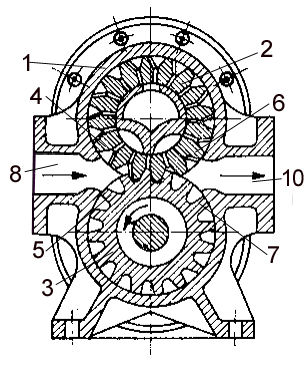
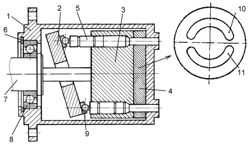
1. Carcasă
2. Roată dințată conducătoare
3. Roată dințată
4. Dinte părăsind camera de aspirație
5. Dinte intrând în camera de aspirație
6. Dinte intrând în camera de refulare
7. Dinte părăsind camera de aspirație
8. Aspirația pompei
9. Refularea pompei
1. Casing
2. Driving gear-wheel
3. Gear-wheel
4. Tooth leaving the suction chamber
5. Tooth entering suction chamber
6. Tooth entering delivery chamber
7. Tooth leaving the delivery chamber
8. Suction side
9. Delivery side
Pompele cu roți dințate au o mare răspândire datorită robusteții și fabricației relativ simple. Cu toate acestea folosirea lor este limitată de presiunea maximă posibilă ( 200 daN/cm2). Pe scurt acestea constau din două roți dințare care angrenează. Aceste roți dințate se rotesc într-o carcasă. Una din roți primește mișcarea de la motorul de acționare. Camerele cu volum variabil se formează între zona de angrenare, dinții 4, 5 respectiv 6,7, carcasa și capacele pompei. Fiecare dinte care părăsește camera de aspirație lasă un vacuum pentru lichid spre a pătrunde înăuntru. Lichidul intră in spațiile dintre dinți și este transportat împrejur până la camera de refulare. Un fenomen asemănător se produce în camera de refulare, cu deosebirea că dintele intră în cameră și forțează lichidul în afară în colectorul de refulare.
The gear-wheel pumps are widely used because of their robustness and their quite simple construction. Even so, their use is limited by their maximal pressure (cca. 200 daN/cm2). In brief they consist of two interlocking gear wheels. These gear-wheels are rotating in a casing. One of them receives the movement from the driving motor. The variable volume chambers are formed between the interlocking area, teeth 4,5 respectively 6,7, the casing and pump covers. Each tooth which exits the suction chamber leaves a vacuum for liquid to flow into. The liquid enters the spaces between teeth and is carried round to the delivery chamber. A phenomenon like that happens in the delivery chamber with the exception that the tooth enters the chamber and forces the liquid out into the delivery tube.
Pompa produce un flux pulsator. Fluxul este cu atât mai uniform cu cât este folosit un număr mai mare de dinți.
The pump produces a pulsating flow. The larger the number of teeth is used, the more uniform the flow is.
Debitul este egal cu suma volumelor dintre dinții roții dințate.
The quantity of flow equals the sum of space volumes between gear wheel teeth.
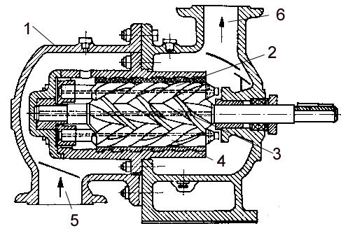
1. Carcasă
2. Șurub condus
3. Șurub conducător
4. Șurub condus
5. Aspirația pompei
6. Refularea pompei
1. Casing
2. Screw
3. Driving screw
4. Screw
5. Suction side
6. Delivery side
Pentru a îmbunătăți uniformitatea debitului se folosesc pompe cu șurub. (fig. 10.3) Acestea sunt mai silențioase în funcționare, au o durată de utilizare mai lungă, greutate și dimensiuni mai reduse, o construcție compactă și un debit uniform.
To improve the flow uniformity screw pumps are used. (fig. 10.3) They are more silent in operation, they have a longer life time, smaller weight and dimensions, a compact design and a continuous flow.
Pe scurt aceasta constă din două sau trei șuruburi care angrenează și care se rotesc într-o carcasă.
In brief it consists of two or three interlocking screws which are rotating in a casing.
Acest tip de pompă se folosește de obicei pentru combustibil greu sau alte fluide cu viscozitate mare.
This type of pumps is usually used for heavy oil or other fluids with high viscosity.
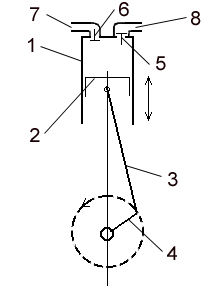
Pompă cu acțiune simplă (fig. 4)
1. Cilindru
2. Piston
3. Bielă
4. Arbore cotit
5. Supapa de refulare
6. Supapa de aspirație
7. Aspirația pompei
8. Refularea pompei
Single-acting pump (fig .4)
1. Cylinder
2. Piston
3. Connecting rod
4. Crank shaft
5. Discharge valve
6. Suction valve
7. Suction side
8. Delivery side
Pompă cu acțiune dublă (fig. 10.5)
1. Cilindru
2. Piston
3. Tija pistonului
4. Prima cameră hidraulică
5. A doua cameră hidraulică
6. Valva de refulare a camerei a doua
7. Valva de aspirație a camerei a doua
8. Valva de refulare a primei camere
9. Valva de aspirație a primei camere
Double-acting pump (fig. 10.5)
1. Cylinder
2. Piston
3. Piston rod
4. First water chamber
5. Second water chamber
6. Second chamber discharge valve
7. Second chamber suction valve
8. First chamber discharge valve
9. Second chamber suction valve
Cele mai utilizate dintre pompele alternative sunt pompele cu piston. Aceste pompe constau în principal dintr-un piston care se mișcă într-un cilindru și un mecanism de distribuție cu valvule unisens. La pompele mari putem întâlni cămașă de cilindru și segmenți pentru a etanșa pistonul și îmbunătăți frecarea. Pistonul este acționat de un arbore cotit prin intermediul unei biele. Uzual arborele cotit este acționat de un motor electric.
The most frequently used of the reciprocating pumps are the piston pumps. These pumps consist mainly of a piston moving in a cylinder, and a distribution gear with non-return valves. At the big pumps we can find a cylinder liner and piston rings to seal the piston and improve friction. The piston is driven by a crank shaft by means of a connecting rod. The crank shaft is usually driven by an electric motor.
În acest tip de pompe volumul camerei pompei este mărit prin coborârea pistonului. Aceasta creează un vacuum în care lichidul este tras din conducta de aspirație prin valva de aspirație. Pistonul este apoi ridicat, micșorând volumul camerei pompei și forțând în afară prin supapa de refulare în conducta de refulare.
In this kind of pumps the volume of the pump chamber is increased by lowering the piston. This creates a vacuum into which the liquid is drawn from the suction pipe through the suction valve. The piston is then raised, decreasing the volume of the pump chamber and forcing the liquid out through the delivery valve into the delivery pipe.
Pistonul poate fi de tip “cu lame de contact” când este prevăzut cu una sau mai multe valvule unisens permițând lichidului să treacă într-un singur sens. În acest caz supapele atașate în exterior dispar.
The piston can be of bucket type when it is provided with one or more non-return valves permitting the fluid to pass in one direction only. In this case the externally attached valves disappear.
Dacă mărimea pistonului este egală cu cea a tijei pistonului pompa este o pompă cu piston plonjor (plunjer). Pompa cu piston plonjor funcționează în același mod ca pompa cu piston.
If the size of the piston equals the size of the piston rod the pump is a ram pump. The ram pump works in the same manner as the piston pump.
Dacă lichidul este aspirat numai la deplasarea pistonului intr-un sens, pompa se numește cu acțiune simplă, dacă însă lichidul este aspirat în ambele sensuri avem o pompă cu acțiune dublă. În acest caz avem două camere de lichid, una de-o parte a pistonului și una de cealaltă parte, fiecare fiind prevăzute cu o valvulă unisens de aspirație și o valvulă unisens de refulare. În consecință lichidul poate fi aspirat și refulat pe fiecare cursă.
If the liquid is only sucked on the piston one-way the pump is a single-acting pump, but if the liquid is sucked in both ways we have a double-acting pump. In this case there are two water chambers, one on one side of the piston and one on the other side, each of them being fitted with a non-return suction valve and a non return delivery valve. Consequently the liquid can be drawn and discharged on each stroke.
1. Carcasă
2. Disc înclinat
3. Butuc
4. Placă de distribuție
5. Pistonaș axial
6. Garnitură
7. Ax de antrenare
8. Lagăr de rostogolire
9. Articulație sferică
10. Fereastră de aspirație
11. Fereastră de refulare
1. Casing
2. Inclined disk
3. Cylinder block
4. Distributing plate
5. Axial plunjer
6. Gasket
7. Driving shaft
8. Roller bearing
9. Spherical joint
10. Suction opening
11. Discharge opening
Pompele rotative cu pistonașe (fig. 10.6) sunt frecvent utilizate în sistemele hidraulice atunci când sunt cerute presiuni și debite mari.
Rotary plunger pumps (fig. 10.6) are widely used in hydraulic systems when high values of pressure and flow are required.
Aceste pompe constau din câteva pistonașe plonjoare dispuse axial sau radial. Când pistoanele sunt dispuse axial acestea intră într-un butoiaș rotitor care alunecă pe o placă de distribuție care este fixată pe carcasa care înconjoară butoiașul. Pistoanele sunt articulate cu un disc înclinat prin articulații sferice.
This pumps consist of several ram pistons disposed radially or axially. When the pistons are disposed axially, they enter a rotating cylinder block which slides on a distribution plate fixed on the casing surrounding the cylinder. The pistons are articulated with an inclined disk with spherical joints.
Butucul este rotit de un motor electric. Placa de distribuție are două deschizături astfel încât jumătate din pistonașe sunt în contact cu o deschizătură în timp celelalte sunt în contact cu cealaltă deschizătură. O deschizătură duce la conducta de aspirație, iar cealaltă la conducta de refulare.
The cylinder is turned by an electric motor. The distribution plate has two openings so that half of the pistons are always in contact with one of them, while the others are in contact with the other opening. One opening leads to the suction pipe and the other to the delivery pipe.
Înclinația discului dă o mișcare alternativă pistonașelor. Fiecare pistonaș comunică cu o deschizătură pentru o jumătate de rotație și cu cealaltă deschizătură în cealaltă jumătate. Aceasta înseamnă că jumătate din pistonașe sunt în cursa de aspirație, iar cealaltă jumătate în cursa de refulare.
The inclination of the disk gives a reciprocating movement to the pistons. Each piston communicates with an opening for half of a rotation and with the other opening on the other half. This means that half of pistons are on the suction stroke and the other half on the discharge stroke.

Susținem dezvoltarea abilităților tehnice, pentru învățământ de calitate și un viitor mai luminos.
Un super site pentru învățat termeni tehnici în engleză
Pentru a susține cauza noastră puteti puteți să ne cumpărați cărțile sau să faceți donatii.